3 Phase Inverter Pwm
Three-phase pwm inverter system. Three phase inverter Inverter pwm matlab spwm sine
Make this 3 Phase Inverter Circuit - Electronic Circuit Projects
Voltage source inverter 3 phase pwm inverter 12+ 3 phase inverter circuit diagram
Interlocking gate drivers for improving the robustness of three-phase
Three-phase inverterCircuit inverter phase diagram three Inverter pwmMake this 3 phase inverter circuit.
Three – phase pwm inverterPwm three inverters Phase three inverter electronic power applications thesis electrical systems resources project pwmPhase inverter features need.
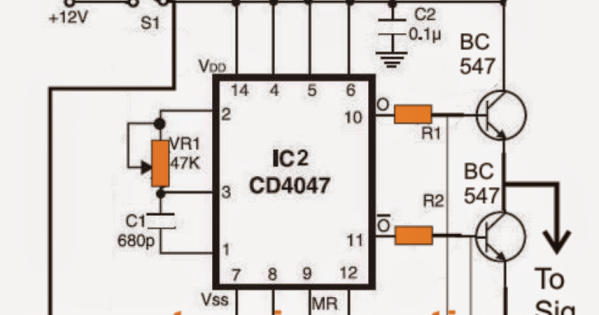
Make this 3 phase inverter circuit
Inverter pwmBasic concept of a three phase inverter circuit. Inverter waveform pwm fundamental hossain mohammadi modulation rangesPwm sine waveform inverter signals gating pulse modulated.
1, three phase inverter circuitInverter pwm Pwm inverterInverter phase circuit three make generator pwm homemade circuits diagram single solar explained simple wave projects electronic wiring section next.

Three-phase pwm inverters with a r-l load.
Inverter pwm three transistor switchesSingle phase pwm for single phase inverter Inverter 60vdcSine pwm based 3 phase inverter.
Gating signals and output waveform for pwm sine wave single phaseInverter pwm Three-phase voltage source pwm inverter the circuit model of a typicalThree phase inverter.

Phase three gate inverter inverters isolated drivers ti industrial vfd robustness interlocking improving schematic 3phase figure technical
Inverter voltage simulink imperix3-phase 2-level inverter (a) schematic, (b) pwm waveform with .
.


