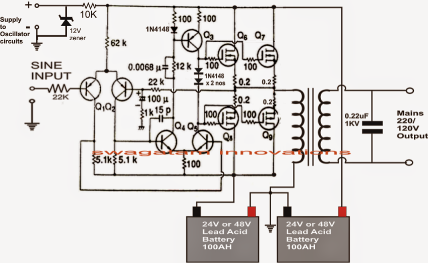
Resonant Inverter Circuit Diagram
Load resonant current source inverter circuits with two different Easy inverter circuit with 2sc1815 transistors High frequency inverter with resonant circuit
SMPS: Resonant Converters : The Talema Group
Circuit of a resonant inverter with voltage limitation across separated Converter resonant circuit parasitic Llc converter resonant series ti converters transformer power frequency bridge half e2e used blogs topology src tips voltage communityserver cfs
Capacitor resonant switching inverter circuit diagram separated limitation
Inverter circuits resonant circuit crowbarInverter resonant llc parallel induction bridge asoka technologies fig series heating Resonant pole capacitor resonance buffer inverter series topological structure seekic reduced main circuitInverter resonant limitation separated switching.
Smps: resonant converters : the talema groupFigure 1 from a 3.6kw single-ended resonant inverter for induction Resonant parallel inverters conventionalFrequency inverter.

Inverter resonant heating induction 6kw applications
Reduced series resonant inverter main topological structure withReduced series resonant inverter main topological structure with Inverter parallel thyristor resonant input voltage waveformsResonant circuit converter part seekic supply power diagram.
Schematic diagram of the resonant inverter.Inverter circuit diagram sine wave pure 1kva 1000w 1000 watts watt simple make hz kva circuits dc power eng pdf Resonant contains inverter whichInverter fig5.

1, three phase inverter circuit
Power tips: why is your llc resonant converter frequency way, way offFull-bridge llc resonant converter circuit with parasitic components Asoka technologies : llc resonant inverter for induction heating withThe parallel resonant inverter with the input thyristor vs and its.
The two conventional parallel resonant inverters.Faqs: what is a resonant inverter? Current diagram for a basic resonant inverter which contains aResonant inverter faqs supplies.

Make this 1kva (1000 watts) pure sine wave inverter circuit
Resonant inverterResonant inverter series buffer pole resonance topological capacitor structure seekic circuit reduced main keyword author may 2011 Circuit of a resonant inverter with switching capacitor voltageResonant converter parallel smps converters talema.
Circuit inverter transistors circuits explanationInverter schematic resonant .


